From: Patrick Jankowiak (eccm@swbell.net)
Date: Wed Sep 25 2002 - 22:00:13 PDT
For those inclined to do some electronics work themselves, I present a switching regulator design which converts 10-15VDC to 6.3VDC regulated. It is easily adapted to convert 24VDC to 12VDC with some
minor changes. Nothing's very critical in the circuit and it was made from cheap surplus parts.
This circuit type is well known and is called a self-exciting switching regulator. I got the idea from an ARRL ham radio handbook, 1991, page 27-1. That unit takes in about 20V and puts out 13.8 at
5A. Check the library for that one!
The circuit of mine was built for a tube type audio amp which I used in my vehicle, and everything except the switch transistor and the inductor fits on a small circuit board.
Higher currents such as 25-50A would require an inductor rated for the current, an larger free-wheeling diode, and maybe 3 or 4 large transistors in parallel for the switch instead of one. These scale
very well.
Here's the text explaining how it works, and the reference to my schematic image below. The whole article about the amplifier including more pictures of this power supply is at
"http://www.montagar.com/~patj/tubeart.htm"
Sure, by the time you build it and tweek it for 24V input and 12V output, maybe you will spend $50 for parts and $100 for your time, but the satisfaction is what counts.
=========
TEXT:
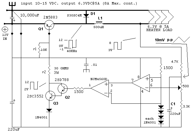
The four 6146 tube heaters require 6.3 volts DC at 5 amps total. Heater voltage is an important factor in tube life. The vehicle's electrical system can vary from 12 to 14.5 volts, therefore, a simple
dropping resistor would not provide correct heater voltage under all circumstances, in addition to generating 30 watts of heat. A buck-type switching regulator was designed, and is shown in figure 3.
A goal was to avoid the necessity of using special IC's and complicated circuitry. The inductor is a surplus 1mh, 8 amp unit. Several inductors were tried, and 500uh to 2mh ones worked well also. An
important aspect of the construction of such a regulator is that the wiring shown in bold should be heavy-gauge wire, such as #12. A low impedance path for current from the negative end of the input
capacitor C1 to the diode D1 is essential to stability. The regulator works as follows: When power is applied, there is no voltage present at the output, and the reference voltage across the 4 diodes
is 2.5V. Because of this, the op-amps, which are operated in open-loop for maximum gain, present a high voltage level at pin 1. This turns on the Darlington-connected pair of Q2 and Q3, which turns on
Q1. Voltage from the 12V supply is presented to L1, and current begins to flow through L1, charging C2 and providing power to the load. As soon as the load voltage reaches 6.4 volts, pin 6 of the
op-amp exceeds 2.5 volts by a few millivolts, and the op-amp's output at pin1 goes to near zero volts. This turns off Q2, Q3,and Q1. Current has been flowing in L1 and now that Q1 has turned off, the
voltage at the collector of Q1 would go very negative due to the imminent collapse of the magnetic field of L1, possibly damaging Q1, if it were not for the diode D1. D1 provides a path for L1's
decreasing current flow until Q1 is turned back on. Now, with Q1 off, the load voltage drops to 6.2 volts. The voltage presented to the op-amp pin 6 is now a few millivolts less than the 2.5 volt
reference, and the op-amp again brings its output on pin 1 high, starting the process over. The frequency of operation is about 40 KHz and the efficiency is 90%. The key to this efficiency is to
saturate Q1 during its ON time, reducing its dissipation. The 3.3K resistor in the low side of the error amplifier divider chain may need trimming in order to allow the 500 ohm pot to adjust the
output over the range of 5-7V. In the case examined here, a 22K resistor was placed across the 3.3K resistor. The heater voltage should be 6.3V +/- 5%, per the RCA Transmitting Tube Manual. Note that
the measured heater supply waveform is a square wave, rather than a DC voltage. The frequency and duty cycle vary slightly but the averge output voltage remains reasonably constant. Purists may wish
to add a filter section comprised of a 1mh inductor in series with the heaters, bypassed by a 10,000uf capacitor. In that case, the voltage feedback connection should remain directly at the
'unfiltered' output of the 1mH inductor to assure stable regulator oscillation.
Figure 3. Heater Power Supply Circuit.
"http://www.montagar.com/~patj/fig3.gif"
NOTE: the schematic shows a 500uH inductor. I used a 1Mh unit.
Although heatsinks with 80 square inches of area were used for the heater and bias supply switch devices and mounted under the chassis, the devices dissipate so little heat that they could be bolted
directly to the chassis. It was desired to "hide" any solid-state devices from the external appearance of the amplifier.
This archive was generated by hypermail 2.1.4 : Wed Apr 23 2003 - 13:21:25 PDT